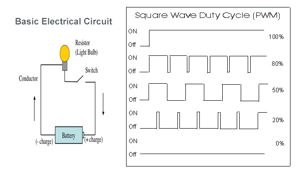
The following shows the non-inverted, fast PWM waveform and its Fourier transform. So most likely I will want to implement a Phase Correct PWM Mode. TCCR1B = (1< non-inverted fast PWM on OC1B with prescalar of 1 for 15.98KHz fast PWM \\begingroup\ PeterJennings my intent is to send a PWM signal to an electronic speed controller for a brushless 3-phase motor. The 20% duty cycle is obtained by loading the OCR1B register with 200. The frequency is obtained when the pre-scalar is set to 1, and 1000 is loaded into the OCR1A register. In this Arduino Fast PWM example, we generate non-inverted Fast PWM on Arduino pin 10(OC0B pin), with frequency of 15.98KHz and duty cycle of 20%. The Arduino has 3 timers and 6 PWM output pins. The PWM functionality is often shared with other pin functionality. The frequency of the generated Fast PWM signal is given by, When you look in the data sheet or the pinout of the processor these PWM capable pins have names like OCRxA, OCRxB or OCRxC (where x means the timer number 0.5). By manipulating the chips timer registers directly, you can obtain more control than the analogWrite function provides. After adding the TIMER1 interrupt I discovered I had problems with motor control, which I finally tracked down to using pins 11 & 12 for PWM simultaneously with using TIMER1 for timed interrupts. The ATmega168P/328P chip has three PWM timers, controlling 6 PWM outputs. So lets say if i want to have 62kHz frequency PWM (which would be using timer0), this would disturb my functions like millis(), delay() and micros(), as said by MarkT. I'm using an Arduino Mega to control motors via PWM and Adafruit DRV8871 motor drivers. Allows you to set any PWM frequency, pre-delay, TOP. As jurs said that the absolute maximum PWM frequency for 8-bit PWM output is something like ca. When the output is cleared we get non-inverted Fast PWM waveform and when the output is set we get inverted Fast PWM waveform. PWM library ( GitHub) a powerful library that allows you to change the PWM frequency on ATmega48 / 88 / 168 / 328 / 640 / 1280 / 1281 / 2560 / 2561 microcontrollers, of which 328 is on UNO/Nano/Mini and 2560 is an Arduino Mega. In this mode, the TOP is 0x00FF when the timer/counter 1 OCR0A/OCR0B is loaded with count value, it counts up to the 0x00FF and when match occurs, the output on OC0A/OC0B pin can be either be cleared or set on compare match. The Timer 1 has the following Fast PWM modes:ġ) Mode 5: 8-bit Fast PWM with TOP at 0x00FFĢ) Mode 6: 9-bit Fast PWM with TOP at 0x01FFģ) Mode 7: 10-bit Fast PWM with TOP 0x03FF OCR1A/OCR1B depending upon the channel A or B used However, this will not work if you want to measure the interval between 2 streams of PWM inputs because it would not be possible to differentiate between next LOW/HIGH caused by the PWM signal, of the first stream and the start of the second stream of pulses.The Timer/Counter 1 is configured by using the following registers.ģ. It lets you learn more intermediate but useful programming techniques in Arduino. Subtract the first value from the second value and you have the elapsed time Use External Interrupt Use Timer Interrupt. When you detect the second input becoming HIGH save the value of millis() and since STM32 architecture are totally different I found my self lost here, I found few documents explain STM32F1 implementation of arduino code e. When you detect the first input becoming HIGH save the value of millis(). Hi all, I tried before to run DAC on ATtiny85 after I found code that uses timer/interrupter to generate PWM signal similar to PCM to have 8bit/8khz sound output from M-C. To time the interval between input pulses normally you would do :


#Arduino pwm timer code#


 0 kommentar(er)
